Line card
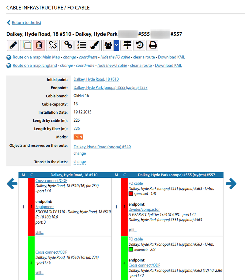
The line card displays information about the cable with extensive accounting options and further actions.
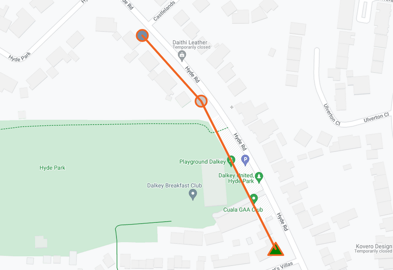
The cable line starts and ends at the infrastructure objects. In this way on coverage map you can see the route of this line (for those cable lines that have the map display set up) and in case the line does not follow a straight line between the start and end point - change this route.
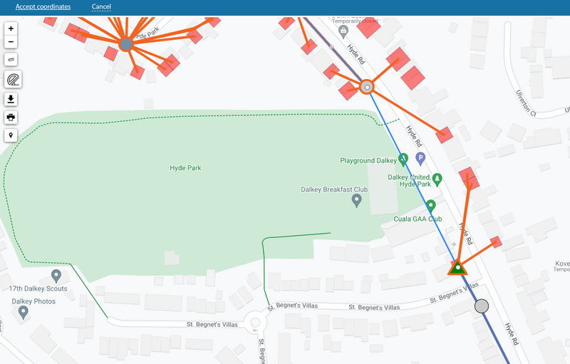
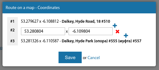
It is also possible to modify by manually entered coordinates
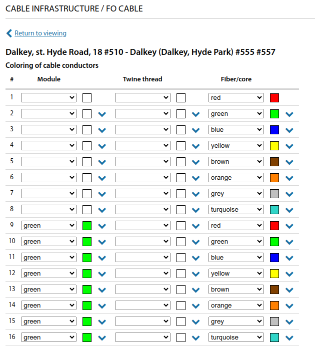
For lines it is possible to specify fibre/core colours. When adding a line, you can make a selection from the existing cable catalogue and then the line will be created with the predefined colours.
For optical lines, you can also specify attenuation values on the OFs.
At the bottom of the line card there is a fibre/core commutation table, where you can see the commutation of fibres/core on the left and right side of the line. This also allows you to view the entire commutation route on any fibre/strand.
If there is a need - it is possible to break the line at the specified infrastructure object and then the line will turn into two lines, the first of which will remain the existing line but with the termination point at the break point, and the new line will start at the break point and end at the termination point of the original line.
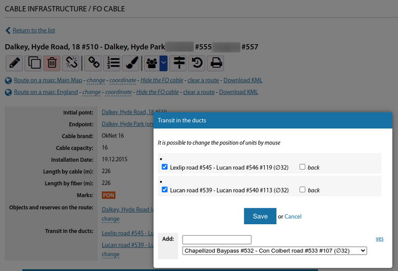
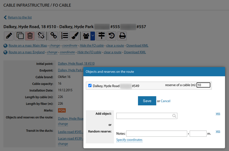
The line can be laid through cable ducts and have arbitrary cable stocks as it is laid out
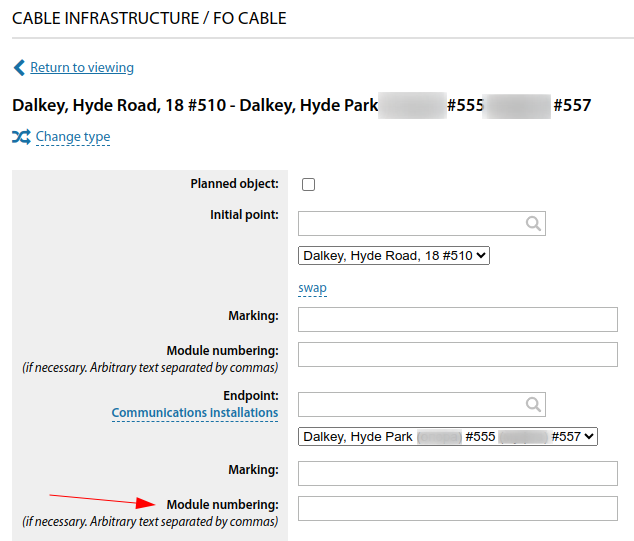
Starting from version 3.17, it is possible to specify arbitrary numbers/letters for optical module numbers in the cable line card.
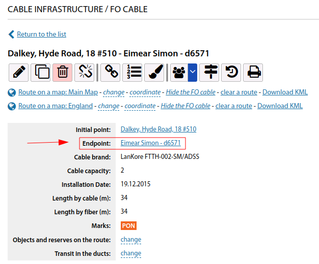
Also, starting from version 3.17, it is now possible to view and work with the commutation scheme on the user.
Starting from version 3.19:
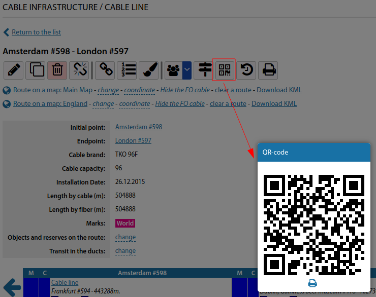
QR code generation option added for cable lines
Starting from version 3.20:
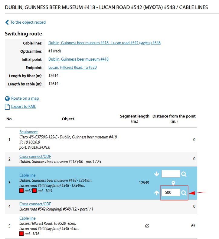
For cable lines, the ability to display a point on the map based on entered distance along the route has been added (e.g., for identifying a break point)
To do this, it is necessary to access the switching diagram in the fibre menu and select the "Switching route" option.
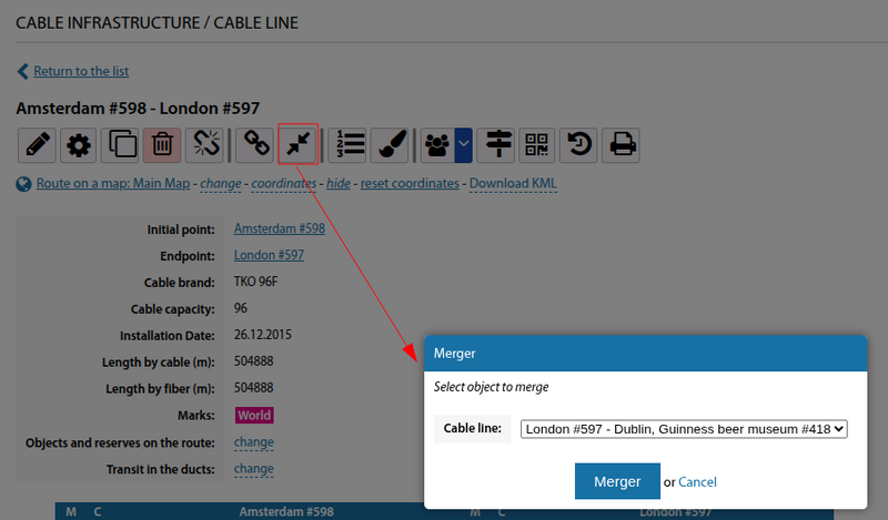
For cable lines, the possibility to merge them has been added
