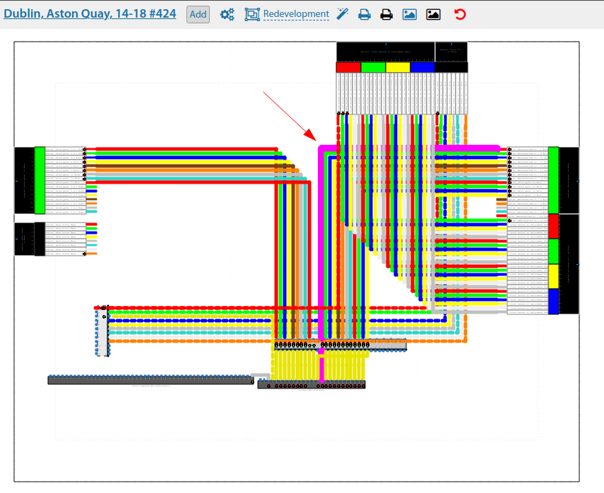
Switching scheme
See also: Commutation schemes
See also: Switching redevelopment
The switching interface allows you to clearly see all switching in Communication nodes/Fiber Optical Junction Boxes between each other and with equipment.
Tools are available to add objects and perform commutation directly in the scheme. When you click on an object in the scheme, the corresponding menu appears with additional actions.
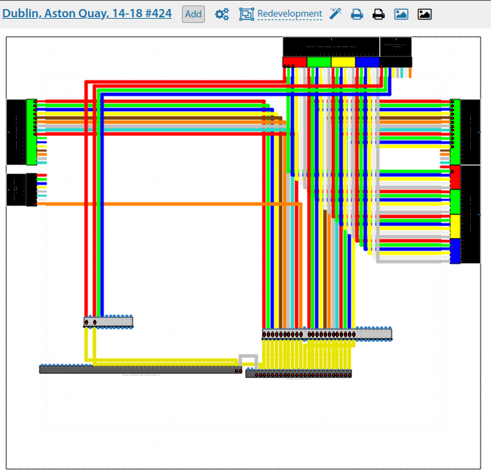
By consecutive mouse clicks on two objects that can be connected (fibres/core/adapters/ports) a menu for commutation/welding of such objects appears.
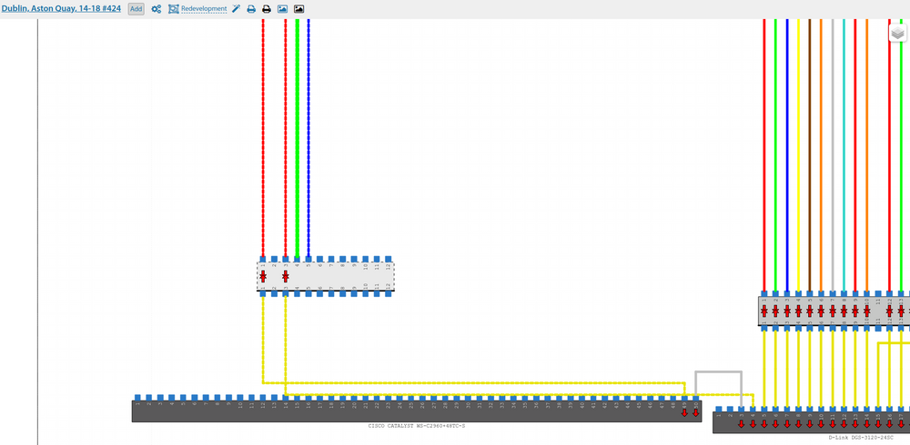
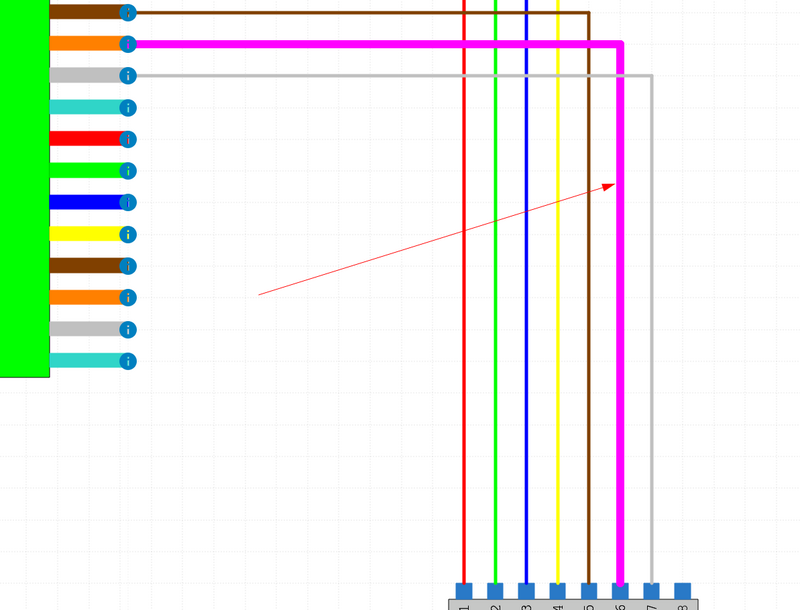
The commutation is shown by a line between the two objects in the colours of the two fibres/strands involved, or in yellow if it is equipment adapters/ports. The line has three points, by clicking on which it is possible to shift the drawing route of this line. If you do not change the coordinates of the switching point, the system will try to align the lines to the grid.
When selecting an object that has already been switched, it is possible to break the connection of this object or reset the coordinates of such connection (actual if they have been changed).
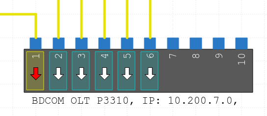
When viewing the scheme, all ports/adapters/fibres, which are connected to the equipment at the end points, have white arrows on the scheme, pointing at which you can get a hint about the connection and view the equipment card.
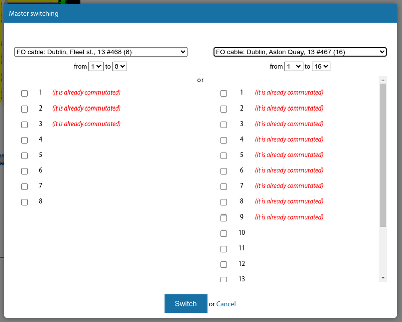
For switching cable lines with a large number of fibres/core or ODFs/Crossovers with a large number of adapters there is a so-called "Master switching "
The output of the planned facilities on the scheme is slightly different from the actual existing facilities. See Planning
Switching scheme in large nodes can be significant in size, so when printing it will be scaled to A4 format. However, when printing - the scheme is exported to png/svg-image, which can be saved and further printed in the required size or work with it in other software products.
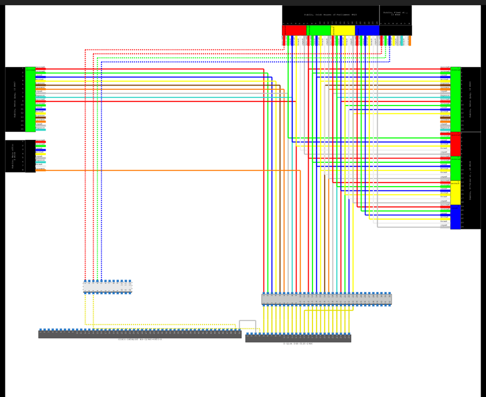
Starting from version3.17, there is a possibility of cancelling operations in the switching scheme. Many actions can be cancelled in the switching scheme of a communication installation. Changing the position of cables, crossovers, devices, their direction, switching, etc. The key combination "Ctrl+Z" is supported.
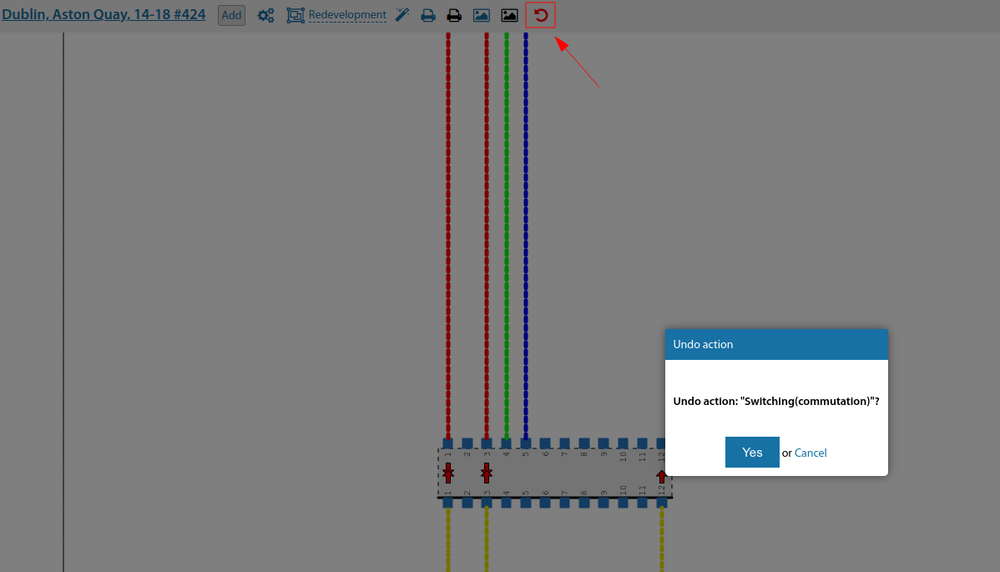
Also, it is now possible (from version 3.17) to display text information about the end point of connection of this fibre in the switching scheme on the fibres of cable lines. This allows you to quickly see where all the fibres go and whether they are busy when viewing the scheme.
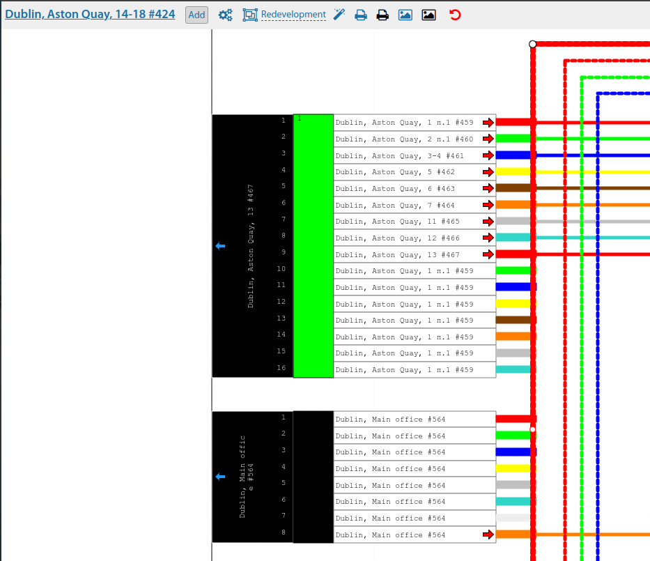
In the switching scheme of the communication installation, you can immediately change the note on the cross/ODF.
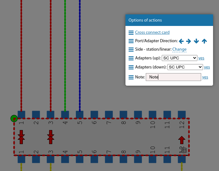
Also, a link to the general switching menu for that port has been added to the menus on the switch ports.
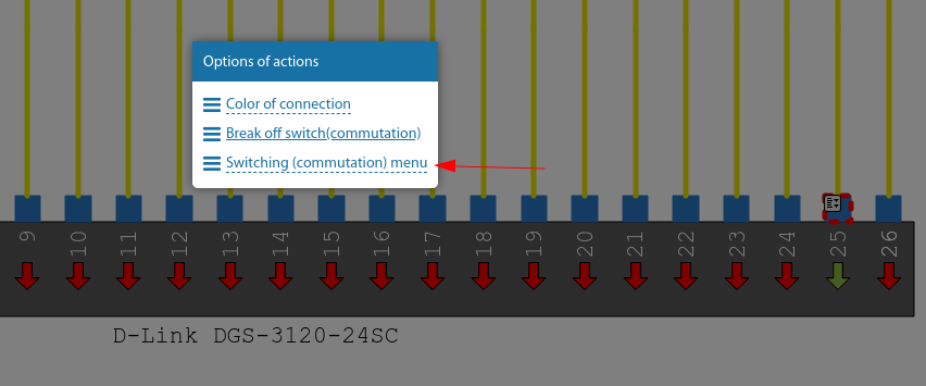
Starting from version 3.18:
The option to cancel switching of all fibres/core cables/cross cables between each other has been added to the switching scheme.
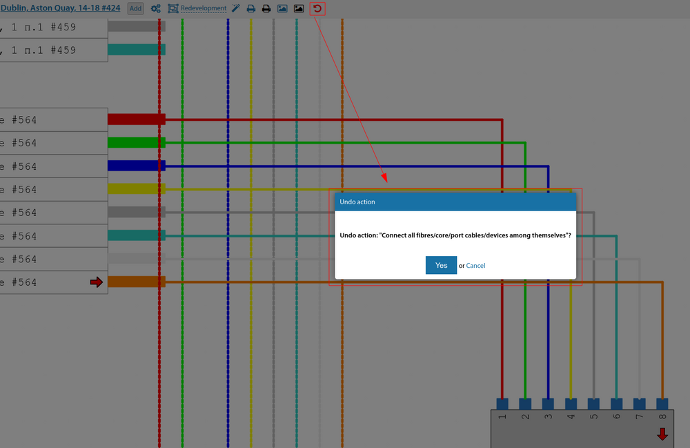
The option to cancel a switching break has been added to the cancellation of actions in the switching scheme of a communication installation.
When re-switching in a switching scheme - cancelling a switching operation - restores the previous switching operation as well.
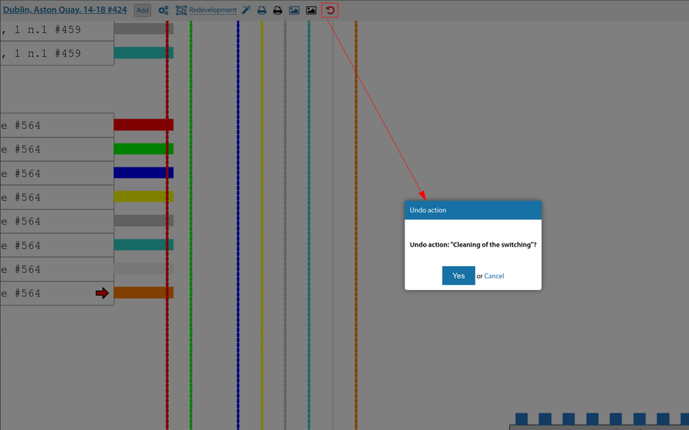
Coloured "switching pointers" have been returned to the switching diagram to indicate which equipment is currently active/inactive.

The switching scheme on the divider port outputs the ONU RX signal levels (dBm) for the connected ONU.
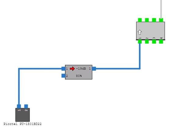
When you click on a fibre/patch cord in a switching scheme, it not only changes its thickness but also its colour.
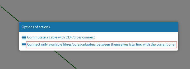
Added ability to switch all free fibres/core of a cable line/ ODF/cross adapter to another object. I.e. mass switching between only unoccupied objects.
Also, in the switching scheme, the signal level on the user's ONU is displayed in the pop-up hint for the subscriber.
There are separate uplink/downlink ports for the equipment.
If you click on a switching line in the global switching scheme, the entire switching route of that line is highlighted at once.
