PON EN: различия между версиями
Нет описания правки |
Нет описания правки |
||
| Строка 9: | Строка 9: | ||
PON lines are documented in [[FOCL]] ''(see also ''[[Line routes on a map]]'' | PON lines are documented in [[FOCL]] ''(see also ''[[Line routes on a map]]'' | ||
[[Файл:|thumb|800px|center]] | [[Файл:2023-06-13_18-07.png|thumb|800px|center]] | ||
For FOCLs with different numbers of OF, it is possible to specify their representation in different colours. It is also possible to specify a specific colour for any FOCL. | For FOCLs with different numbers of OF, it is possible to specify their representation in different colours. It is also possible to specify a specific colour for any FOCL. | ||
| Строка 15: | Строка 15: | ||
It is also possible to view PON lines separately - just select the required map layer. | It is also possible to view PON lines separately - just select the required map layer. | ||
[[Файл:|thumb|800px|center]] | [[Файл:2023-06-13_18-07_1.png|thumb|800px|center]] | ||
In PON the commutation is performed using [[Divider/Splitters|optical dividers]]. The [[Switching Scheme|Switching Scheme]] has separate tools for adding dividers and their relative switching. | In PON the commutation is performed using [[Divider/Splitters|optical dividers]]. The [[Switching Scheme|Switching Scheme]] has separate tools for adding dividers and their relative switching. | ||
[[Файл:|thumb|800px|center]] | [[Файл:2023-06-13_18-20.png|thumb|800px|center]] | ||
A [[Structural scheme|structural scheme]] can be constructed for each object, which is especially relevant for PON-trees. This scheme will reflect the calculated attenuation values. | A [[Structural scheme|structural scheme]] can be constructed for each object, which is especially relevant for PON-trees. This scheme will reflect the calculated attenuation values. | ||
| Строка 28: | Строка 28: | ||
* attenuations on welded and mechanical joints | * attenuations on welded and mechanical joints | ||
[[Файл:|thumb|800px|center]] | [[Файл:2023-06-13_18-27.png|thumb|800px|center]] | ||
== Equipment == | == Equipment == | ||
Версия от 15:30, 13 июня 2023
PON (Passive optical network) is a passive optical network technology. The PON access network is based on a tree-like fibre-optic architecture with passive optical splitters at the nodes and is a cost-effective way to guarantee broadband access to information. At the same time, PON architecture has the necessary efficiency of network node and bandwidth scaling, depending on the current and future needs of users.
The ERP "UserSide" has a set of tools for documenting the PON and provides certain convenience in monitoring its effective operation.
Optical communication lines
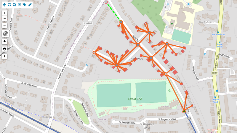
PON lines are documented in FOCL (see also Line routes on a map

For FOCLs with different numbers of OF, it is possible to specify their representation in different colours. It is also possible to specify a specific colour for any FOCL.
It is also possible to view PON lines separately - just select the required map layer.

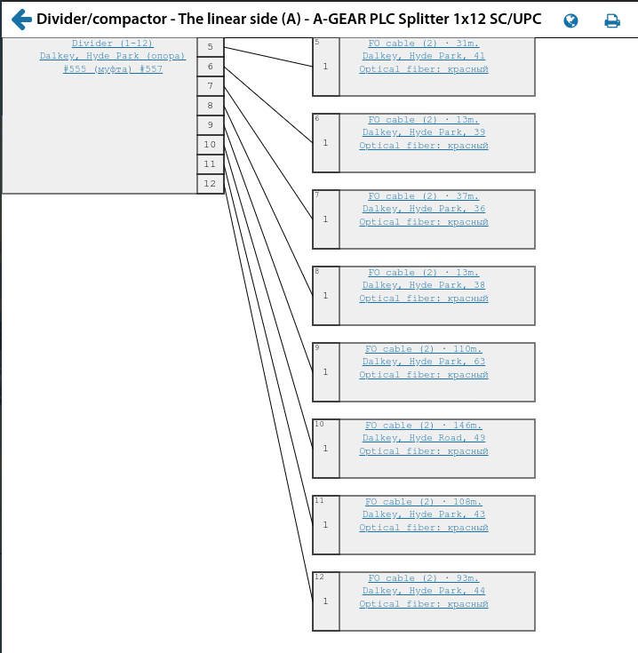
In PON the commutation is performed using optical dividers. The Switching Scheme has separate tools for adding dividers and their relative switching.

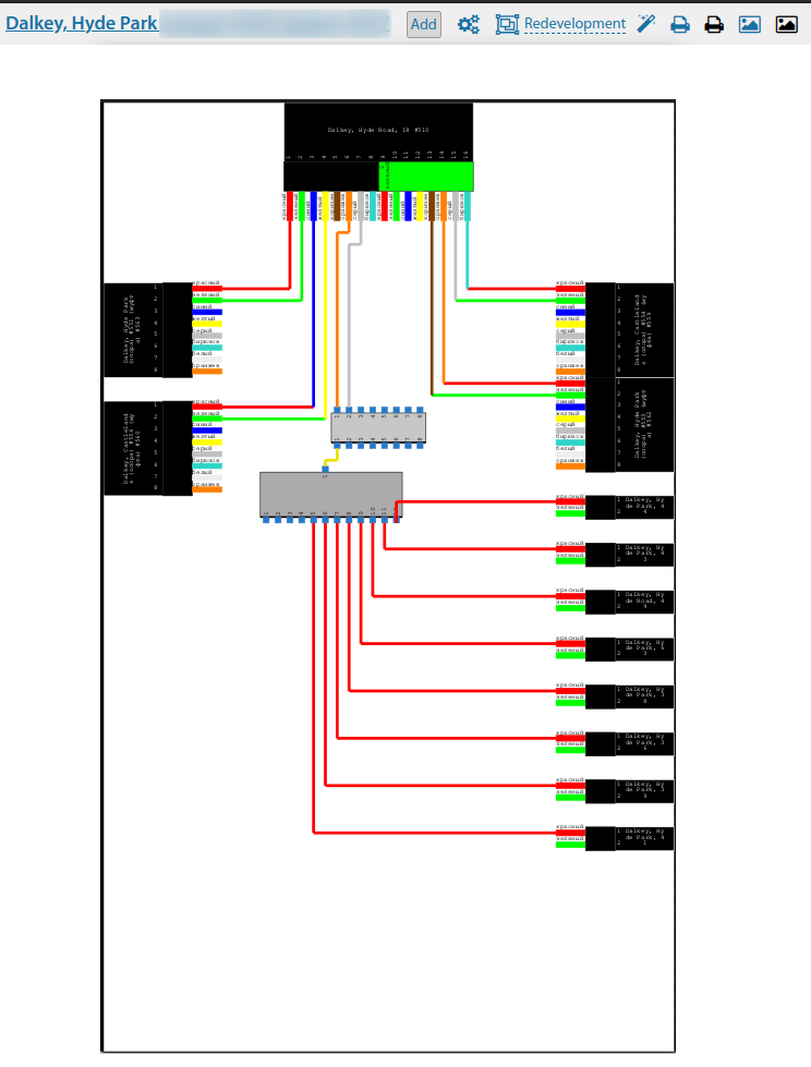
A structural scheme can be constructed for each object, which is especially relevant for PON-trees. This scheme will reflect the calculated attenuation values. It takes into account:
- outgoing power at PON interfaces of OLTs (normative value specified manually)
- division factors on the dividers
- the linear attenuation on the fibre optic cables, taking into account their metreage
- attenuations on welded and mechanical joints

Equipment
The core of PON is the main terminal (OLT). It contains both Ethernet ports for connecting uplink channels and outgoing optical PON interfaces. Quite a lot of information can be retrieved from the OLT. "UserSide" processes OLT data with slightly different algorithms than other switch models, so the data output is more structured for the specifics of PON and this OLT model
See also: ONU
[[Файл:|thumb|800px|center]]
Both for the system and for each OLT it is possible to specify limit values for the optical signal power level. This data is used when generating reports and also for the usm_pon module. (see below). If the current data exceeds the specified limits, the exceeding values will be marked in red.
[[Файл:|thumb|800px|center]]
The end points of the network are the user terminals (ONU/ONT). They are usually unmanaged, have no IP address and are often difficult, if not impossible, to capture information from it. However, this is often unnecessary, as all the basic information is stored on the OLT and is stored for each user terminal connected to it, namely:
- PON interface number
- incoming signal strength
- distance to OLT
- status of the ONU uplink port and traffic through it
- status of other ONU ports
When opening an ONU card, the ERP "UserSide" automatically retrieves the necessary information from the upstream OLT and displays it in the ONU card, which visually looks as if it is being monitored directly from the ONU
[[Файл:|thumb|800px|center]]
Monitoring
A separate module usm_pon is used for monitoring. It periodically interrogates all available OLTs and monitors the following indicators:
- the output of the optical signal from the OLT to the ONU is outside the permitted limits
- detecting ONUs on the OLT that are not listed in the UserSide (unknown)
- detection of ONUs which are registered simultaneously on two OLTs
When mismatches are detected, information messages will be displayed on the main page
[[Файл:|thumb|800px|center]]
A list of connected ONUs/ONTs can be viewed on the OLT:
[[Файл:|thumb|800px|center]]
The system supports recording the history of signal level changes by ONU
[[Файл:|thumb|800px|center]]
A list of ONU/ONTs can be displayed on a map (based on the coordinates where this ONU/ONT is installed)' with their signal levels
[[Файл:|thumb|800px|center]]
Also see: FAQ. ONU/ONT activity